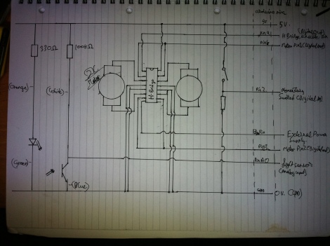
Circuit diagram:
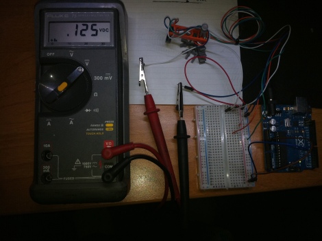
Connected the light sensor to a power supply, using the information shown above, and measured the varying voltage levels across it using a multimeter, recording the values in particular for over both a white and a black surface, and by simple calculations, see how they correspond to the values gotten from the micro controller (0-1023).
1023/5=204.6
204.6×0.125(value gotten from multimeter)
=25.5,
Which is quite close to the value received from the micro controller, so the light sensor circuit is functioning properly.
And a link to Waverd Danger Mk 1
here.

